
Standard reference dipoles (SRDs) have been adopted as an essential tool for evaluating sites used for electromagnetic compatibility (EMC) testing and calibration of associated antennas. The modular form of NPL’s SRD enables evaluation of sites with direct reference to traceable VNA (vector network analyser) measurement of the Balun and numerical model of the elements.
NPL is offering three options which are available to buy:
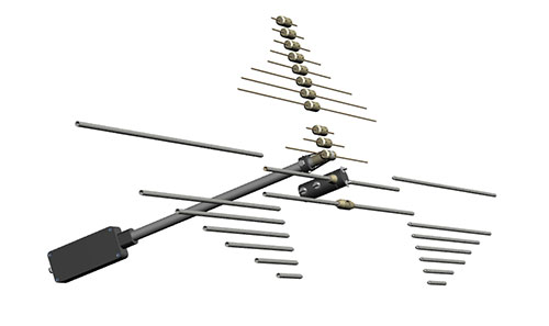
The SRDs are made on site at NPL, and are designed to be modular and user friendly. They are either tuned or broadband performance in the range 30 – 1000 MHz. The SRDs are ultimately traceable to NPL’s Reference Test Site:
| Specifications | |
| Frequency Range | 30 - 1000MHz |
| Return Loss | >18dB |
| Power Handling | 1 W |
| Uncertainty in site insertion loss (SIL) at resonant frequencies |
0.5 dB |
| Uncertainty of antenna factor (AF) at resonant tuned frequencies |
0.2 dB |
| Uncertainty of antenna factor over the swept frequency bands |
0.35 dB |
| Balun Length | 0.8 m approx. |
The above uncertainties apply to the deviation between the computed SIL (and AF) and the measured SIL over a continuously welded metal plate of minimum area 30 m x 20 m.

Software
The executable software CAP2010 models the coupling between two wire antennas, calculating the site insertion loss between a pair of dipole antennas and their antenna factors either over an ideal ground plane or in free space. Download the software and user manual for free.
Don’t see what you are looking for? Our diverse skill set enables us to provide bespoke solutions. Please contact us to discuss your requirements.
Our research and measurement solutions support innovation and product development. We work with companies to deliver business advantage and commercial success.
Contact our Customer Services team on +44 20 8943 7070